Concentrator Plant Layout: How a Processing Plant Is Arranged
A concentrator plant layout is a three-dimensional decision that fixes gravity flow, crane reach and future expansion long before concrete is poured.
Discuss your project
Overview
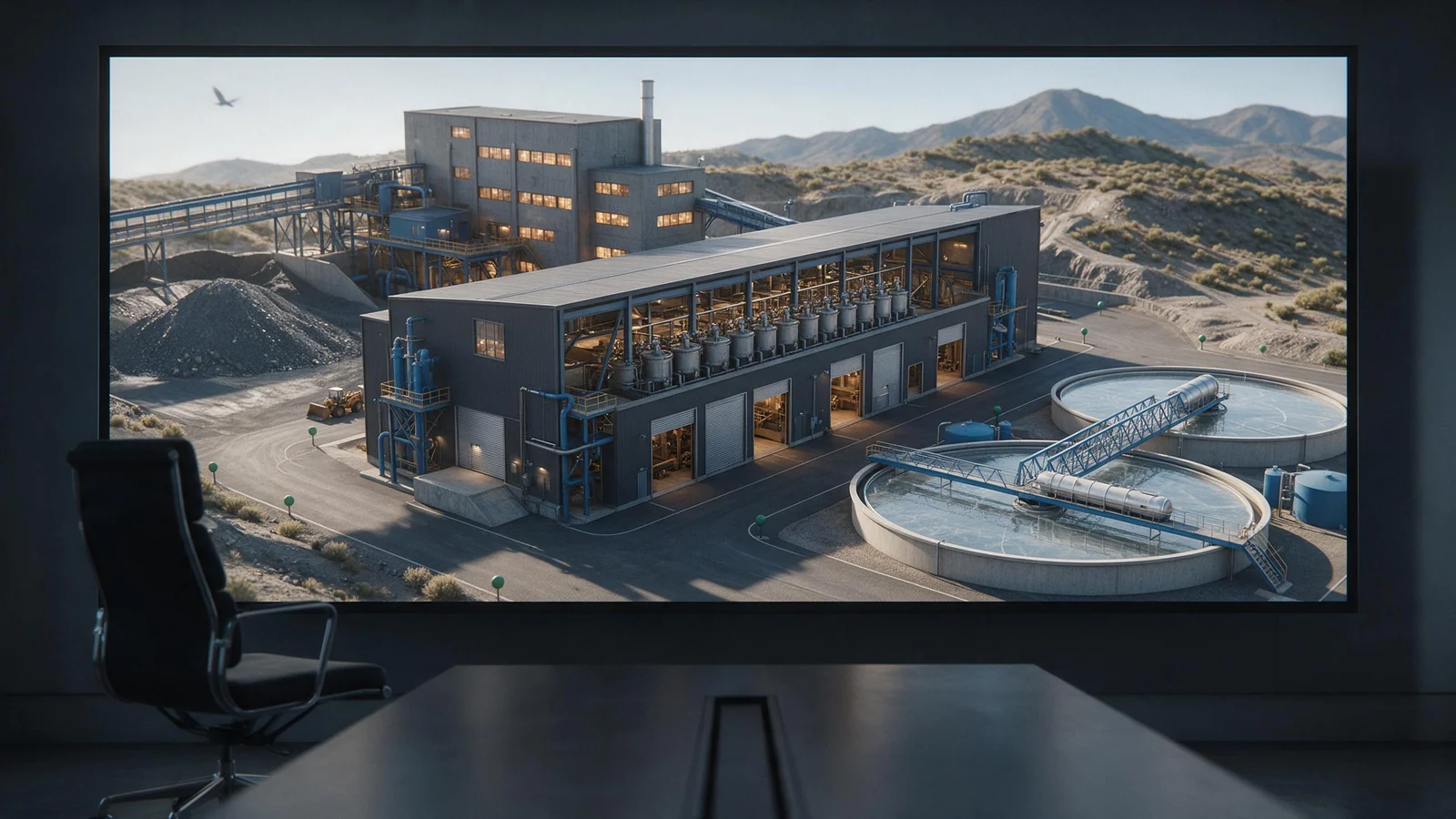
Say a mine owner asks what a concentrator plant layout actually has to achieve on a 1,000 t/d copper project. That's the right question, because the layout is where cost and operability get locked in. A concentrator plant layout is not an architectural exercise. It's a flow sheet drawn in steel and concrete.
What a concentrator plant layout has to achieve
It has to let gravity do as much work as possible. Every lift you install is a pump, a motor, a power cable and a maintenance point that will cost money for the life of the mine. You want the primary crushed ore to fall into a stockpile, then into the mill feed conveyor, then into the mill, without a single unnecessary transfer. Where that isn't possible, you shorten the conveyor and straighten the pipe rack. That's not a small detail. A tangled plot plan adds structural steel, cable tray, pipe supports and operator travel time. It also hides safety hazards in corners that nobody visits until something fails. Good layout also leaves room for a future second line, because mine plans change more often than foundations do.
| Layout approach | What it optimises | What it costs | When it fits |
|---|---|---|---|
| Gravity flow | Pumping energy, pipe length, operator travel | Elevated steel, taller structures | Hilly sites with space |
| Compact modular | Civil work, installation time, transport | Less future expansion room | Remote or fast-track projects |
| Spread stick-built | Access, future expansion, crane reach | Higher civil and pipe costs | Large multi-line concentrators |
Why testwork and the flowsheet fix the layout
Testwork isn't something you do to confirm a layout. It's the thing that determines it. A copper ore that floats fast needs fewer cells and a different arrangement than a high-pyrite ore that needs three cleaning stages. A hard ore dictates a bigger mill and more power, which changes the mill bay crane and the substation location. If you freeze the layout before the flowsheet is proven, you'll pour concrete for a machine that doesn't exist. That mistake costs rework, money and months. Sampling is the first part of testwork; you can read more about representative sampling in our plant sampling guide.
Once testwork fixes the flowsheet, the layout follows the process route, not the reverse. A design team that starts with a pretty site plan and then tries to fit the flowsheet into it will end up with awkward pump boxes and long pipe runs. Mine design work is iterative: the flowsheet informs the plot plan, the plot plan informs the structural steel, and the structural steel informs the capital estimate.
Crushing, stockpile and surge capacity in the arrangement
Crushing is the easiest part to get wrong in a layout, because it's noisy, dusty and heavy. Place the primary crusher close to the mine portal or dump pocket, not across the site. A long feed conveyor from the pit to the crusher simply shifts the bottleneck. After primary crushing, the ore should go to a stockpile with enough live capacity to run the grinding circuit for a shift or two. That decouples mine shifts from mill feed. If the mine stops for blasting or shift change, the mill keeps turning on stockpile inventory. Without that surge, your grinding circuit chokes every time a truck is late.
For secondary crushing, cone crushers are common. The US EPA's crushed stone processing description notes that initial reduction uses jaw, impactor or gyratory crushers, and cone crushers are commonly used for secondary crushing, typically reducing material to about 2.5 to 10 centimetres (1 to 4 inches). EPA crushed stone processing description.
Leave a pad for a future crusher or screen. Foundation pads for a future second line are cheap. Cutting into a live plant to add one is not.
Grinding, classification and flotation circuit arrangement
Grinding and classification are where the layout earns its keep. A ball mill bay needs cranage that covers both the mill and its gearbox, plus laydown space for shell sections and liners. You don't want to realise during a reline that the crane hook can't reach the feed end. Classifiers and hydrocyclones should sit above the next process stage so slurry can flow by gravity into flotation rather than being pumped uphill. The same applies to flotation rows: arrange cells in straight lines, leave reagent dosing lines on a walkway between banks, and keep a clear route for a forklift or a cell removal trolley.
P80 is the size 80 per cent of the mass passes. If the grind target is P80 75 micrometres, the mill and classification circuit are sized around that. The layout must give the mill room to breathe and the operators a straight path to sample and maintain it. Xinhai reports a 2 million t/a spodumene concentrator EPC+M+O project in Zimbabwe where mill throughput exceeded design capacity by 7.6%, equipment utilization reached 95.7%, concentrate grade was stable above 5.5%, and recovery improved from 59.5% to 69%. A layout that supports relining, sampling and pump access is part of why such throughput gains are possible. The design and manufacturing scope behind that arrangement is covered on our plant design and manufacturing page.
Thickener, dewatering and tailings placement
Thickener placement is often decided last and regretted first. Put the thickener between flotation and tailings storage, not on the far side of a ridge. Underflow pumps need to move thickened slurry to a tailings storage facility or filter press. The longer that distance, the more energy you burn and the more pipe you maintain. If you plan dry stacked tailings, place the filter press close to the thickener underflow and give it a big laydown area for cloth changes. Return water from the thickener overflow should flow back to the process water pond by gravity if possible. A pump on the return water line is a sign you've placed something badly.
Think about tailings storage as part of the layout, not an afterthought. The tailings beach and decant location affect where you can put the thickener and the return water pond. If the tailings facility is uphill from the plant, you've made a pumping problem permanent. Good designers route the tailings line and the return water line together, with a common corridor for access and inspections.
Water, reagent and utility systems in the plot plan
Reagent storage is not a corner shed. Collector, frother, flocculant, lime and any cyanide or acid each need containment, ventilation and safe access. Place reagent mixing near the flotation circuit but downwind of offices and control rooms. Keep incompatible reagents in separate contained areas with clear signage. Process water and return water circuits should be laid out as loops, not dead ends, so flow keeps moving and solids don't settle in low points. Power and air lines should follow the same piperack route, not zigzag across roads. The control room needs a view of the flotation floor and the mill bay, but not a window into the reagent store.
That last sentence isn't a joke. Operators respond to what they can see. A control room with a clear view of the mill and flotation allows a faster reaction when a pump trips or a bank starts to sand. If the view is blocked by a tank or a building, you lose those seconds.
Owner checks for a concentrator layout drawing
Before you sign a general arrangement drawing, walk through it as if the plant is running. These are the checks that catch most layout failures.
- Does every piece of equipment on the approved flowsheet appear, with the correct tag number and orientation?
- Do the maintenance cranes cover the full mill bay, filter area and pump floor? Can you lift a motor without removing the roof?
- Are there two escape routes from every elevated platform? Are stairways and ladders placed where operators actually walk?
- Does the surge bin or stockpile hold enough to decouple mine and mill for at least one shift?
- Is there a marked pad for a second line? Are tie-ins shown for future tailings or water expansion?
- Are reagent and fuel stores positioned so spills flow away from people and watercourses?
You'll also want confirmation that machine guards meet point of operation requirements, such as those in OSHA 1910.212. OSHA's interpretation of machine guarding is a useful reference. After layout approval, commissioning will quickly reveal whether the arrangement actually works. Our mineral processing plant commissioning guide covers that handover stage.
One final check: confirm the design basis. Xinhai's mine design institute holds a Class B metallurgical industry design qualification and states that it designs to JORC, NI 43-101, VALMIN, GB, Eurocodes, US and Australian standards, using 3D BIM coordination and VR/AR digital delivery. That's the kind of documentation you want to see in the drawing pack.
Frequently asked questions
What is a concentrator at a mine?
A concentrator is the processing plant on a mine site where run-of-mine ore is upgraded into a saleable concentrate. It uses physical and chemical processes, usually including crushing, grinding, separation such as flotation or gravity concentration, and dewatering. The waste, or tailings, goes to a tailings storage facility; the concentrate is shipped to a smelter or further processing.
What are the four main types of mineral processing?
A common four-way split is gravity separation, magnetic separation, froth flotation and hydrometallurgical leaching. In practice, most concentrators combine two or more of these, plus comminution and dewatering, depending on the ore.
What is a copper concentrator?
A copper concentrator is a mineral processing plant that upgrades copper ore, typically sulphide or oxide, into a copper concentrate using crushing, grinding and flotation. The concentrate grade depends on ore mineralogy and smelter contracts. Oxide copper ores may instead use heap or tank leaching followed by solvent extraction and electrowinning.
What should an owner check in a concentrator layout drawing?
Check that the drawing matches the approved flowsheet and equipment list, that crane coverage includes every major item, that escape routes and stairways are shown, that surge capacity decouples mine and mill, and that space for future expansion and tie-ins is marked. Also confirm reagent and fuel storage are positioned safely.